|
Intellivision Games
Game Info & Reviews
Software
Mattel Electronics
Action
Arcade
ECS
Gaming
Intellivoice
Learning
Space
Sports
Strategy
1983
PlayCable
INTV Corporation
Blue Sky Rangers, Inc.
Imagic
Activision
Coleco
Parker Brothers
Atarisoft
Dextell, Ltd.
Interphase
Sega
Test
Demo
Independent
2600 Connection
5-11under
AtariAge
Blah Blah Woof Woof
CollectorVision
Côté Gamers
Dr. Ports
Elektronite
Freewheeling Games
Good Deal Games
Homebrew, Inc.
The Immortal John Hancock
Intelligentvision
Intellivision Collector
Intellivision Revolution
Inty‑Home
Kai‑Magazine
Left Turn Only
Opcode
Zbiciak Electronics
Unknown
Intellivision, Inc.
Sears
Digiplay
CBS Electronics
Hardware
Mattel Electronics
INTV Corporation
Sears
Tandy
GTE Sylvania
Independent
Overlays
Text Table
Mattel Electronics
INTV Corporation
Imagic
Activision
Coleco
Dextell, Ltd.
Interphase
Intellivision, Inc.
Trade Lists
Want List
Other Stuff
Technical & Repair Info
Odds & Ends
Old Gaming Magazines
Site Updates
Contact INTV Funhouse
|
Why I Had To Learn To Do This
Skip this crap and gimme the info!
Much to my chagrin, one day my workhorse unit, a trusty old INTV System III,
seemed to provide excessive resistance to the insertion of an IntelliVoice unit.
I'd just gotten a brand new copy of World Series Major League Baseball
(yep, opened that shrink-wrapped sucker!), and was dying to try it out. I'd been
wanting that game for 18 years! I also wanted to see if putting the hardware
together in different combinations made a difference to the behavior of the game.
So, pumped for truly amazing baseball action, I turned on the system. But it
didn't work! In fact, NOTHING worked. ARGH! My cherished system had just died
for no reason! O, yea, the pain and suffering! Verily, did I nearly shed a tear!
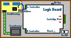
After a deep, calming breath, I dried my eyes and decided to look into the
cartridge port, that mysterious point of contact between our cold reality and the
fantastic realm of the Intellivision. Lo, what to my distraught eyes did appear,
but crinkled and crushed, mashed, bent, and twisted connectors therein! The contacts
had somehow gotten caught up, and were pushed into the edge connector,
shorting several of the contacts in the upper and lower rows together.
Upon inspection, I found that it was impossible to bend the contacts back to
the correct positions. So, the quest began to locate a 44-position edge connector,
two rows of 22 connection points each.
Fortunately, I work at a company that creates new hardware and software. A
colleague of mine happened to have a sample 44-pin edge connector available to
donate to my cause. The distance between contacts was just right (0.1 inches), a
well as the distance between solder tails (0.156 inches), and it was made for the
correct card thickness - basically, it's the same as an ISA bus edge connector
you'll find in older PCs in terms of the thickness of the printed circuit card
(the cartridge) and distance between connections. To determine if this was even
worth pursuing, I pulled the old broken connector out and put in the new one.
Once I connected that puppy up, the machine played like a dream! Thus, the quest
for the 44-pin right-angle edge connector began, leading to this web page!
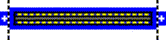
Unfortunately, the connector looked like this:

Top View of Edge Connector
|

Side View of Edge Connector
|
What you need, however, is for the pins you connect to your Intellivision
logic board to be bent at right angles, like this:

Top View of Edge Connector
|

Side View of Edge Connector
|
Forget about trying to bend 44 pins like this yourself. You need to do it
quite precisely. So, I located an adequate replacement and put it in.
In my case, it was easy to identify the problem because it happened while I was
using the unit. It was working, then, after pushing extra hard to insert a game
or peripheral, it stopped working. You could also see bent wires inside the
cartridge port. Your machine won't boot games, it will give garbled or blank
screens at best.
To replace your cartridge connector, you'll need the following items.
Tools & Supplies
- Soldering iron with a small, narrow tip, and larger, flatter tip (any basic model will suffice)
- Desoldering braid (or wick)
- Solder suitable for electronics
- Philips screwdriver
- Needle-nose pliers
- Wire cutters, or a small cutting tool like a razor blade or X-Acto knife
- Possibly 1/4" Hex Nut driver (some Master Components used hex-head screws internally)
- Multimeter (capable of measuring up to 20 V DC and continuity)
- 2 small C-clamps (optional)
Parts
DISCLAIMER: Do this at your own risk! It worked for me. I'm assuming you've got some familiarity with the guts of an Intellivision, and can handle a
soldering iron and the tools involved here.
I've done this repair on a "standard" Intellivision (i.e. any version except
for the Intellivision II). There is no reason why it shouldn't work just as well
on an Intellivision II.
- Open the Intellivision Console
Follow this link for step-by-step instructions.
- Remove the Defective Cartridge Port
Use the small soldering iron tip and the
desoldering braid to remove the cartridge port. Start from the
"bottom" side of the board - i.e. the side with all the pins sticking
out of it. This may not completely loosen the socket. Therefore, you may need to
check from the top side, too.
Note: Be extremely careful to avoid
inadvertently shorting two connections together when melting and removing the
solder. This will cause endless nightmares when you attempt to use your system again.
Tip: Remember, when removing solder, lay the
desoldering braid over the solder, and put the tip on the braid.
Note: Due to the age of the printed circuit board (PCB)
your Intellivision uses as its substrate, be careful when pulling pins to avoid
pulling up the actual circuit traces printed on the board. If you damage an
eyelet around a hole, or pull up a trace, you can use a small bit of wire
(such as a strand from telephone or CAT-3 or CAT-5 Ethernet cable) to solder a
jumper to another solder point.
Note: These pins may be tough to pull unless you get
all of the solder out. You may need to set the board on its edge, hold
the soldering iron to the connection with one hand, and pull the pin out from
the other side using the needle-nose pliers. This will bend up
the connection pins on your cartridge port, but hey, it's already broken!
Note: The edge connector that is your cartridge port
is almost certainly not held down by any adhesive of any kind.
Therefore, once you've desoldered and pulled all the pins, the part should come
off easily. I've not yet seen a connector held down by any kind of glue. If you
do encounter that, use the razor blade with extreme caution to cut the
part away from the logic board.
- Prepare the New Part
If your replacement part is like the ones I've used, it has extra
mounting eyelets on each side of the part. You will need to trim these off, as
indicated by the dashed lines in this image. I used wire cutters
and a razor blade to cut away the extra material.
After trimming, test a few cartridges to ensure that they can slip into the slot.
You won't need to actually insert the cartridge into the connector completely,
just make sure that the eyelets are sufficiently trimmed. The thermoplastic
polyester insulator cuts and scrapes pretty cleanly. (And you thought polyester
was only good for cheap suits!)
- Install the New Cartridge Port
The part is actually installed "upside down" - i.e. the same way as the
main chips on your logic board. It will be a little bit of a challenge to get all
44 of the pins to slip into the holes. I had to put some pressure on the part
because the distance between the two rows of pins wasn't quite 100% right. However,
it did (and does still) work perfectly. Be certain to solder all 44 pins, and do
not introduce any new shorts between pins. Despite its apparent fragility, once
you solder all 44 pins through the board, it easily bears the load you put on it
when inserting or removing a cartridge.
Note: The replacement part I
list here doesn't reach all the way to the edge of the logic board like the
original one does, but it does provide adequate contact area to correctly read
cartridges, an IntelliVoice, or the Entertainment Computer System. I've tried it
with all the different brands of carts I have (Imagic, Activision, Coleco, etc.)
and it works perfectly.
Tip: I found that using two small C-clamps to hold the
new part down on the logic board made soldering it much easier.
Note: Make sure that the part lies perfectly flush with
the logic board! Otherwise, your carts might not be able to fit!
- Test Continuity
To make sure your handiwork has been successful, use an Ohmmeter
to verify that the contact point that the cartridge will touch is connected to the
PCB. You might want to take this opportunity to check the voltages coming from the
power supply, too.
- Test the port
Assuming no other damage has been incurred, put the logic board back into
its metal housing (not necessary on Intellivision II), reconnect the cables, and
try out a game. If you need to reset your unit, use a pencil to push the reset
switch. If your machine doesn't work, double-check the continuity and the connections
to the power conditioning circuit. Also, verify the voltages being supplied.
- Reassemble the unit
Assuming you've succeeded in restoring your Intellivision, I'd suggest
closing up the logic board again, then putting the unit back together. Voila!
The only concern I have about this repair is that the part may not be rated for
heavy use - i.e. a large number of insertions and removals. After several months
of moderate use, I have not encountered any signs of significant wear.
A suitable, but not perfect, replacement part can be purchased at
Digi-Key. It costs around $7-$8 + shipping.
Specific Part Information:
Digi-Key Part Number: EBC22DRAN-ND
Vendor: Sullins Electronics Corp.
Manufacturer Part Number: EBC22DRAN
Mounting: Through Hole, Right Angle
This link
might get you to the data sheets.
This link
might get you the exact data sheet from the manufacturer.
If those don't work, try the following search at their site:
Keywords: edge connector
Then, on the filter page, chose Number of contacts to be 22 (22 pairs = 44 total)
Someplace I did find a better match, but the part is obsolete and out of stock. I forget which web site it was. If you find a better replacement part, please let me know, and I'll update these
instructions put your info here if you'd like.
|