|
Intellivision Games
Game Info & Reviews
Software
Mattel Electronics
Action
Arcade
ECS
Gaming
Intellivoice
Learning
Space
Sports
Strategy
1983
PlayCable
INTV Corporation
Blue Sky Rangers, Inc.
Imagic
Activision
Coleco
Parker Brothers
Atarisoft
Dextell, Ltd.
Interphase
Sega
Test
Demo
Independent
2600 Connection
5-11under
AtariAge
Blah Blah Woof Woof
CollectorVision
Côté Gamers
Dr. Ports
Elektronite
Freewheeling Games
Good Deal Games
Homebrew, Inc.
The Immortal John Hancock
Intelligentvision
Intellivision Collector
Intellivision Revolution
Inty‑Home
Kai‑Magazine
Left Turn Only
Opcode
Zbiciak Electronics
Unknown
Intellivision, Inc.
Sears
Digiplay
CBS Electronics
Hardware
Mattel Electronics
INTV Corporation
Sears
Tandy
GTE Sylvania
Independent
Overlays
Text Table
Mattel Electronics
INTV Corporation
Imagic
Activision
Coleco
Dextell, Ltd.
Interphase
Intellivision, Inc.
Trade Lists
Want List
Other Stuff
Technical & Repair Info
Odds & Ends
Old Gaming Magazines
Site Updates
Contact INTV Funhouse
|
DISCLAIMER: Do this at your own risk!
It has worked for me countless times over many years - these beasts seem pretty
rugged. I'm assuming you've got some familiarity with the guts of an Intellivision,
and can handle a soldering iron and the tools involved here.
- Soldering iron with a small, narrow tip, and larger, flatter tip (a basic unit will suffice)
- Desoldering braid (some say wick)
- Solder suitable for electronics
- Philips screwdriver
- Possibly 1/4" Hex Nut driver (some Master Components used hex-head screws internally)
These instructions are applicable to a "standard" Intellivision - i.e. any
version except for the Intellivision II. An Intellivision II doesn't
encase the logic board in a tin can, so it's a lot easier.
- Open the Intellivision Console
There are six "Phillips" - type screws to remove on the bottom of the
unit. Remove all of them using the screwdriver.
Then, putting the unit "right-side-up" again, remove the top cover.
Slide the controllers through the top of the unit.
NOTE: Use extra care when lifting the top off the
INTV System III and Super Pro System units. These sport a
power-on LED and the wires connecting the LED to the main unit are easily
detached from the LED or the unit itself! That turns into another repair project.
- Remove Controllers and Logic Board Assembly
There are six more screws holding down the plastic where the controllers
rest, as well as securing the main logic board to the base of the unit.
On some units, rather than Phillips-type screws, 1/4" hex head screws were
used. Remove the screws, then the plastic part.
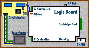
You will see a power conditioning circuit, which has some large capacitors on it.
On the edge closest to the main board, two different connections to the logic board
are made. One wire has a plastic connector that slides over two metal pins.
Disconnect this. The other connection is a 5-pin ribbon-cable type of connector
that plugs into a small socket.
Disconnect with extreme care! On these older units,
the connectors on this cable can become brittle and break away from the main
logic board itself, or from the connector. If you do break one of these
connections, you'll have to repair that, too, or your Intellivision will not
work. See this page for tips on
how to repair this problem should it arise.
Once you've disconnected the two power cables, lift up the left side of the main
logic board assembly and unplug the controllers.
NOTE: When you reconnect the controllers, remember
that the brown wire should be closest to the "back" of the unit.
- Open the main Logic Board Assembly
After you have disconnected the controllers and other connections, you
should be able to lift the logic board unit out of the main system. Put the
large flat solder tip into your soldering iron and heat it up.
You will probably need to desolder 10 solder points as well as
the large blob of solder near the cartridge port in order to open the unit.
(OK, I confess - most times I just break it off by the cartridge port. :-) )
Usually, the top cover of the logic board unit is silver, and the bottom cover
black. You will need to remove both if you plan to access the cartridge port.
Note: Be careful not to let solder bleed onto the main
logic board or to cause any inadvertent connections between different points
on the logic board.
Note: Although these units seem quite robust, you
might want to take standard electrostatic discharge prevention measures to avoid
any unintentional damage to the electronics in the unit. In my personal experience,
these things are very tough, but ESD is a tricky beast best avoided.
|