|
Intellivision Games Software Hardware Overlays Trade Lists Other Stuff |
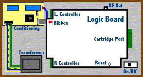
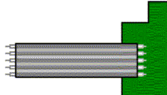
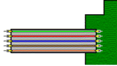
Why I Had To Learn To Do ThisSkip this crap and gimme the info! The controllers on my old INTV System III were behaving poorly after my unit saw heavy action in the dorms in my sophomore year of college. This was back in the last days of INTV Corp's existence, back in 1987-88. In about 1990, I decided to attempt to repair the controllers by purchasing some conductive coating - some expensive stuff sort of like paint, but that is a good conductor of electricity. The stuff sure looked like the material used on the circuit traces in the mylars inside the controllers... Well, finally in about 1995 I got around to trying the repair, having moved many more times, including out of the country, and then across it. After "repairing" some of the broken traces, one controller failed to work at all. I figured some sloppy tracing on my part had shorted a couple of the conductive traces on the mylars. Eventually, I ended up opening the unit and removing the controllers from the main logic board, to test which circuits closed when certain buttons were pressed, et. al. What I mapped out turned out to be the same as what can be found in the Intellivision FAQ - I just based my pin assignments on what was at the socket connector at the end of the cable rather than the contacts inside the controller itself. My efforts were fruitless. I found no problems when testing the controllers via an Ohmmeter. In a rush for some reason, I partially reassembled the INTV System III and threw it back into the closet. I had an Intellivision II to fall back on, which was OK as long as I didn't feel ike playing those awesome Coleco games. Five years later, I dragged the beast back out. That's when I inadvertently learned that it's possible to repair the INTV System III (and other models) with the wires from a 6-conductor telephone cable, or CAT 3 or CAT 5 Ethernet cable! (That is, if you can't easily get some FlexiCable and appropriate support parts.) How is that, you ask? Well, I was cleaning up my INTV System III master component and attempting to finish my controller repair project. If you've ever disassembled a 3504 (or 2609) to detach the controllers, you'll notice that the main logic board is connected to a small power circuit board (the one with the big capacitors on it) with a small, 5-conductor ribbon-type cable. The cable doesn't have a decent connector on it - not much better than five bare wires that insert into a 5-pin socket. In my haste to test the controllers - having forgotten the way they're supposed to connect - I was repeatedly removing and reattaching them with different orientations of socket relative to the pins. When shifting the logic board to connect the right-hand controller, the ribbon cable broke away from the solder points on the main logic board in several places. Well, that little ribbon cable is just BARELY long enough as it is, so there wasn't enough of it left to re-solder it onto the main board. That, coupled with a ridiculously oversized soldering gun, led to the mutilation of the original cable. Hmm, what to use for a replacement? Having added my own extra Ethernet and telephone lines when our house was under construction, the idea popped into my head that the conductors in those cables seemed about the right size. The conductors proved sufficient - in fact probably higher gage than the originals - and they fit nicely into the socket on the power supply circuit. It looked ugly when disassembled, but who cares? Worked fine! Well, it turns out my little repair wasn't quite the end of the problem. Whilst firing up Safecracker, my old INTV III went out on me again. I thought for sure it was just that the cart needed cleaning. But no, nothing worked. Upon further investigation, I found that several problems had arisen. One of the small wires had broken loose from the main board - again. Also, it seemed that as the unit heated up, problems got worse. Well, it turns out one of the printed circuit traces on the small power board had broken loose around the solder-through hole. So, I wired a bypass for that, and re-wired the system using an old DE-9 male / female pair to make the thing more easily detachable. While at it, I inserted some insulated blade connectors to the LED, since those wires had been pulled out and reinserted numerous times. Once again, the unit seems fine. Ultimately, the original problem with the unresponsive controller proved to be mechanical. The slot I called "socket 1", which is the "main" pin with which all controller actions eventually close a circuit, wasn't making proper contact with pin 1 on the main logic board. Thus, no controller signals ever reached the main unit. This proved maddening in that when testing the controllers by hand with an Ohmmeter, they seemed to work fine. The solution was to carefully pull out the small spring-loaded contact for socket 1, bend it out a bit, and reinsert it into the plastic case. Works like a champ! So, electrically the unit has remained sound - the only problems have been mechanical and age-related. Usually, the symptom indicating the problem is one of the following:
To determine if this is actually the problem, you'll have to open up the unit. To repair the ribbon cable connector, you'll need the following items: Tools & Supplies
Parts
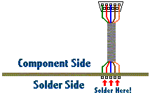
DISCLAIMER: Do this at your own risk! It worked for me. I'm assuming you've got some familiarity with the guts of an Intellivision, and can handle a soldering iron and the tools involved here. This repair is illustrated for "standard" Intellivision units (i.e. any version except for the Intellivision II). There is no reason why it shouldn't work just as well on an Intellivision II.
All of the parts listed here - the wire and D-sub 9 connectors - are available at a TinkerTronics, Digi-Key, or Radio Shack type of store. |
|
|
Page last updated 03-Nov-2018 15:26:03 UTC |