|
Intellivision Games
Game Info & Reviews
Software
Mattel Electronics
Action
Arcade
ECS
Gaming
Intellivoice
Learning
Space
Sports
Strategy
1983
PlayCable
INTV Corporation
Blue Sky Rangers, Inc.
Imagic
Activision
Coleco
Parker Brothers
Atarisoft
Dextell, Ltd.
Interphase
Sega
Test
Demo
Independent
2600 Connection
5-11under
AtariAge
Blah Blah Woof Woof
CollectorVision
Côté Gamers
Dr. Ports
Elektronite
Freewheeling Games
Good Deal Games
Homebrew, Inc.
The Immortal John Hancock
Intelligentvision
Intellivision Collector
Intellivision Revolution
Inty‑Home
Kai‑Magazine
Left Turn Only
Opcode
Zbiciak Electronics
Unknown
Intellivision, Inc.
Sears
Digiplay
CBS Electronics
Hardware
Mattel Electronics
INTV Corporation
Sears
Tandy
GTE Sylvania
Independent
Overlays
Text Table
Mattel Electronics
INTV Corporation
Imagic
Activision
Coleco
Dextell, Ltd.
Interphase
Intellivision, Inc.
Trade Lists
Want List
Other Stuff
Technical & Repair Info
Odds & Ends
Old Gaming Magazines
Site Updates
Contact INTV Funhouse
|
Why I Had To Learn To Do This
Skip this crap and gimme the info!
I don't know about you, but I find it incredibly irritating to play Astrosmash
or Buzz Bombers with interference caused by certain sound effects. I noticed that
a majority of my Intellivision consoles (I'm a sicko who has many variants -
Sears, Sylvania, Tandyvision, etc.) suffered video interference when playing certain
games. This problem can become distracting and irritating enough to actually
warrant a repair!
Note! Often times, the problem is less severe on
one channel. So before proceeding, check to see if your system works better on
the other channel setting. It's a lot easier than replacing the part!
This problem is extremely easy to identify if you have a working Intellivision
and one of the following two cartridges:
For me, Buzz Bombers has always been the best and easiest test case. Simply start
the game. When you "fire" a shot of spray from the spray can, you will
see noticeable interference on your screen. In some units, this can be quite drastic.
In Astrosmash, the "tshh tshh" background tapping sound effect also will
cause interference on the screen. If you see this, your RF unit has decayed and
you may want to consider replacing it.
If you have a "dead" system that doesn't produce a picture at all,
a dead RF unit may or may not be the problem. You may need to remove the RF unit
and test it, or try to tap the video and audio signals directly to see of the logic
board is producing the correct raw signals sent into the RF unit.
To replace your RF Modulator, you'll need the following items.
Tools & Supplies
- Soldering iron with a small, narrow tip, and larger, flatter tip (any basic model will suffice)
- Desoldering braid
- Desoldering tool (slurps up melty solder)
- Solder suitable for electronics
- Philips screwdriver
- Needle-nose pliers
- Possibly 1/4" Hex Nut driver (some Master Components used hex-head screws internally)
- Multimeter (capable of measuring up to 20 V DC and continuity)
Parts
DISCLAIMER: Do this at your own risk!
It worked for me. I'm assuming you've got some familiarity with the guts of an
Intellivision, and can handle a soldering iron and the tools involved here.
This repair is described for a "standard" Intellivision (i.e. any version except
for the Intellivision II). There is no reason why it shouldn't work just as
well on an Intellivision II.
- Open the Intellivision Console
Follow this link for step-by-step instructions.
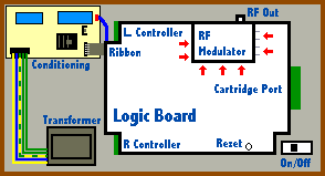
- Remove the Defective RF Modulator
Use the large soldering iron tip, the
desoldering tool and the desoldering braid
to remove the old RF unit. Start from the "bottom" side of the board -
i.e. the side with all the pins sticking out of it. There are four slots arranged
in a diamond pattern, and four wires from the modulator itself. There is a lot of
solder on the four slots - use a desoldering tool to assist in removing this material.
Also, some of the metal tabs inserted through the slots may be twisted slightly to
firmly hold the RF modulator in place on the board, in addition to the solder points.
Use a needle-nose pliers to assist in bending such tabs so
they fit up through the slots in the logic board. Use a
small solder tip to desolder the wires.
The RF modulator looks something like this on the component side of the board.
Note: Be extremely careful to avoid inadvertently
shorting two connections together when melting and removing the solder - especially
on the component side of the board. This will cause endless nightmares when you
attempt to use your system again.
Tip: Remember, when removing solder, lay the desoldering
braid over the solder, and put the tip on the solder wick.
Note: Due to the age of the printed circuit board
(PCB) your Intellivision uses as its substrate, be careful when pulling pins to
avoid pulling up the actual circuit traces printed on the board. If you do damage
an eyelet around a hole, or pull up a trace, you can use a small bit of wire
(such as a strand from telephone or CAT-3 or CAT-5 Ethernet cable) to solder a
jumper to another solder point.
- Install the New RF Modulator
The part is actually installed "upside down" - i.e. the same
way as the main chips on your logic board. If you've done a clean job of removing
the solder from the bottom connection slots and the four wire holes, inserting the
new part should be simple. Use the needle nose pliers to twist at
least two of the tabs (not too much!) that come through the slots on the logic board
to hold the unit in place. It may take a bit of patience to aim the four wires into
the holes on the logic board.
- Test Continuity
To make sure your handiwork has been successful, use an
Ohmmeter to verify that the four wires are properly connected
to the main logic board.
- Test the RF Modulator
Assuming no other damage has been incurred, put the logic board back
into its metal housing (not necessary on Intellivision II), reconnect the cables,
and try out a game. If you need to reset your unit, use a pencil to push the reset
switch. If your machine doesn't work, double-check the continuity and the connections
to the power conditioning circuit. Also, verify the voltages being supplied.
- Reassemble the Unit
Assuming you've succeeded in restoring your Intellivision, I'd suggest
closing up the logic board again, then putting the unit back together. Voila!
Note: If you do not properly and securely close the metal
case around the guts, you may still notice that the resulting picture sent to your
TV suffers some interference. This interference is not due to the fire button being
pressed, but more just a general image degradation.
 |
An exact replacement part can be purchased at
Alltronics. It costs around $4.95 +
shipping. Alltronics has a minimum order of $15.00.
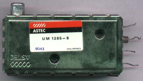
Specific Part Information:
Item Name: VHF Intercarrier Vestigial Sideband Modulator
Manufacturer Part Number: UM1285-8
Vendor: ASTEC
Part Number: 92V017
Follow this link for the page
where the part lives.
If that doesn't work, I did the following search at their site:
Keywords: modulator
So far, this is the only place online that I could locate this part. I don't
the part is at risk of becoming obsolete and out of stock - but it seems that
Alltronics specializes in castoff or older parts, whether overstock or what, I
don't know. If you find another vendor offering this replacement part, please let
me know, and I'll update these instructions put your info here if you'd like.
|